Friday, April 23, 2010

Assembly of Compact 2000 Short Case Axial

Details are extracted from the worksheet

Support Guard 315mm

ELTA2 0.12KW 4PHASE motor

The details are labeled on the motor

Junction box die cast base,base gasket,lid and gasket lid

Compact 2000 short case 315

Wiring instruction for a anti-clock wise rotation

Completed wiring


SR150-14-10PPB-SPAXIAL IMPELLER(150mm,10 plastic blades)

The impeller is placed on the motor

Proper labels are placed on the outside of the casing


Completed casing with impller


Impeller Balancing

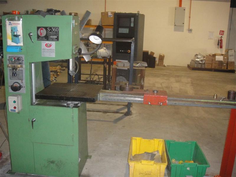
After the impeller is cropped,next it is balanced before it is sent to the assembly department(fixing of casing and motors).
Only 255mm and 350mm impeller requires balancing at this point of operations.

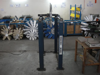
Static Balancer which compromise of two parallel shafts which are fixed to the bearings.The impeller is fixed with the shaft and placed on the balancer.

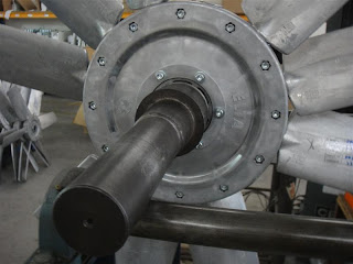
The impeller is pushed and forced to rotate on the shafts.If the impeller rotates on one direction and stops after a while,this indicates that the impeller is already balanced.


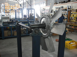
If the impeller does rotate back after a while,this shows that the impeller is unbalanced.

So,further observation have to be done to find where the weight varies on the impeller which causes it to be unbalanced.

After the correction point/s are found,trial weights are placed on that particular points and the rotation of the impeller is observed carefully.

If the impeller does not rotate back after the trial weights are added,this indicates that the impeller is balanced if not,the steps above have to repeated until the impeller is balanced.

Sunday, April 18, 2010

Impeller Cropping

Cutting radius is noted(496mm)

The vertical band saw machine used to crop the impellers

Shaft to pivot impeller and extension bed to rest the impeller

The vertical saw

To set cropping length, measurement
will be taken from the surface of
blade (against the bed rail) to the
centre hole of the shaft

In this case the length is 496mm

Supporting block to hold the impeller while it being cropped

The impeller is placed on the shaft


The impeller is cropped in clockwise rotation

After it being cropped,the will be some remaining on the edge of the impeller

The remainders have to cleaned or shaved

A smoother surface can be obtained


Monday, April 12, 2010

250mm Impeller Assembly

Assembly Jig

Labeled jig

Work Sheet(Details are extracted as below)

H250FPTL(250mm face plate a.k.a FORM A) on the left and H250TL(250mm taper lock hub a.k.a FORM B) on the right

SABL-375 ( left hand aluminum blade 375mm)

AP(aluminum plug suit)

PITCH ANGLE is set to 25 degree

NYLON nut

AIR SWITCH which is used to place the nuts on the jig nut recesses

Nuts are placed on the nut recesses

This unit requires FORM B as the base,so H250 TL is used and the nut recesses are alligned with the nuts

The impeller has a half compliment of blades,so the plugs are placed on each second holes

All of the aluminum plugs are placed

The blades are placed on each vacant hole beside the aluminum plugs(AP)

Complete blades and plugs on the FORM B face plate

FORM A is aligned with the hub of FORM B

After FORM A is attached,all the blades are locked with the retention clips

Blades are locked

Bolts are inserted on each holes on the FORM A plate

All of the bolts are inserted

Each bolts are tighten using the torque screwdriver

Completed 250mm impeller


Assembly team who has helped me.From left Mr Asif,Mr Thin and Mr Muneer.Thank you guys...